Monday, February 23, 2009
Display problem ? Click HERE
Oil - Fouling Factors in [m2K/W]
| Oil Type | Fouling Factor | |
| Gasoil | 0.00009 | |
| Transformer | 0.00018 | |
| Lubrication | 0.00018 | |
| Heat Transfer oil | 0.00018 | |
| Hydraulic | 0.00018 |
Related Post
- Control Around Heat Exchanger
- FAYF - Useful Heat Transfer Equation
- Few Tips on Energy Efficient & Recovery
Labels: Fouling Factor
Sunday, February 22, 2009
Display problem ? Click HERE
Gas / Vapor - Fouling Factors in [m2K/W]
| | Gas / Vapor Type | Fouling Factor |
| Hydrogen | 0.00176 | |
| Engine exhaust | 0.00176 | |
| Steam | 0.00009 | |
| Steam with oil traces | 0.00018 | |
| Cooling fluid vapours with oil traces | 0.00035 | |
| Organic solvent vapours | 0.00018 | |
| Compressed air | 0.00035 | |
| Natural gas | 0.00018 | |
| Stable top products | 0.00018 |
Related Post
- Control Around Heat Exchanger
- FAYF - Useful Heat Transfer Equation
- Few Tips on Energy Efficient & Recovery
- Heat Transfer - Internal and External Flow
- FREE E-book........A Heat Transfer Textbook
Labels: Fouling Factor
Saturday, February 21, 2009
Display problem ? Click HERE

As the price of electricity, natural gas and other fossil fuels continues to climb, chemical processors are more closely examining high-temperature operations and heat-transfer systems to see if more efficiency can be had. In many cases
it can, and, as a result, heat-transfer projects are not only justifiable, but downright attractive.
There was a dialog among a few heat exchanger specialist from Alfa Laval, Paul Muller, Exergy LLC, etc. The dialog mainly discussed on strategy to improve heat transfer efficiency, heat recovery and efficient process control during this high energy price arena.
A few tips have been present :
- The energy crisis results high prices all of the time shorten paybacks. Energy efficient is one of the way to minimize cost
- Energy efficient heat transfer equipment such as Plate Heat exchanger, Gasketed Heat exchanger, Bonded Heat exchanger, etc is one of the option.
- For a service using Shell & Tube (S&T), the overall heat transfer coefficient (HTC) is around 300 Btu/h ft2°F. However, the overall heat transfer coefficient (HTC) for a compact heat exchanger can be improved 3-4 times (~1000 to 12000 Btu/h ft2°F).
- With higher overall heat transfer coefficient, this may translate into less space, smaller installation and handling cost.
- Gasketed Heat exchanger good for maintenance. However shall take additional attention on the compatibility between gasket and fluid.
- All welded or Bonded heat exchanger may be considered if there is gasket & fluid compatible problem
- For laminar flow, heat transfer rate is only the function of fluid thermal conductivity. Operate heat transfer equipment at laminar flow during turndown could significantly reduce it heat transfer rate
- Compact heat exchanger promote turbulence. High turbulence increase heat transfer rate and reduce fouling
- Thus plant releasing hot exhaust gas from burner, boiler, gas turbine, etc to atmosphere may take the opportunity to recover heat
- Improve temperature control in process system would reduce energy usage
Not a CE subscriber... click here to subscribe FREE Chemical Engineering (CE)
Related Topic
- Cooling Water Fouling Factors
- Wire Matrix Turbulator Improve Heat Transfer in ACHE
- Control Valve at Inlet or Outlet of HEX ?
- Tantalum S&T HEX vs Carbon Block HEX...
- Control Around Heat Exchanger
Labels: Heat Exchanger, Heat Recovery
Wednesday, February 18, 2009
Display problem ? Click HERE
Recommended :

Tubular Exchanger Manufacturers Association (TEMA) has developed a series of fouling factor for Shell and Tube (S&T). These fouling factor are generally higher than Plate Heat Exchanger (PHE), why not use S&T fouling factors to size PHE ?
Isn't this approach conservative and guarantee the performance ?
Reason being...
- Oversized Plate Heat Exchanger (PHE) required extra CAPEX and extra Space for oversized PHE
- Tubulence minimise fouling tendencies in correctly sized PHE. Oversized PHE results low actual velocity and increase potential fouling and inefficient heat transfer
- HTRI studies showed PHE fouling significant lower than Shell & Tube Heat Exchanger (S&T)... factor of 6.7
Related Post
- Cooling Water Fouling Factors
- Self Cleaning Heat Exchanger - Online Cleaning ?
- Heat Exchanger Fouling Mechanism, Prevention and Treatment...
- Why Lower Fouling factor in Plate Heat Exchanger ?
- Control Around Heat Exchanger
Labels: Fouling Factor, Heat Exchanger, Plate Heat Exchanger
Tuesday, February 17, 2009
Display problem ? Click HERE
WATER - Fouling Factors in [m2K/W]
| Water Type | Tcw < 50 ° C Tf < 120 ° C | Tcw > 50 ° C Tf > 120 ° C | ||
| v < 1 m/s | v > 1 m/s | v < 1 m/s | v > 1 m/s | |
| Sea | 0.00009 | 0.00009 | 0.00018 | 0.00018 |
| Brackish | 0.00035 | 0.00018 | 0.00053 | 0.00035 |
| Cooling tower with inhibitor | 0.00018 | 0.00018 | 0.00035 | 0.00035 |
| Cooling tower without inhibitor | 0.00053 | 0.00053 | 0.00088 | 0.00070 |
| City grid | 0.00018 | 0.00018 | 0.00035 | 0.00035 |
| River mimimum | 0.00018 | 0.00018 | 0.00035 | 0.00035 |
| River average | 0.00053 | 0.00035 | 0.00070 | 0.00035 |
| Engine jacket | 0.00018 | 0.00018 | 0.00018 | 0.00018 |
| Demineralized or distilled | 0.00009 | 0.00009 | 0.00009 | 0.00009 |
| Treated Boiler Feedwater | 0.00018 | 0.00009 | 0.00018 | 0.00018 |
| Boiler blowdown | 0.00035 | 0.00035 | 0.00035 | 0.00035 |
Tcw = Water temperature
Tf = Fluid temperature
v = Water velocity
Related Post
- Control Around Heat Exchanger
- FAYF - Useful Heat Transfer Equation
- Few Tips on Energy Efficient & Recovery
- Heat Transfer - Internal and External Flow
- FREE E-book........A Heat Transfer Textbook
Labels: Fouling Factor
Display problem ? Click HERE

Recommended :
 In one the recent depleted field debottlenecking project, new Booster Compression unit will be installed to boost the depleted well fluid pressure to meet high delivery pressure while maintaining the production forecast market demand. As this unit will be installed on existing platform, space and weight constraint are the major issues. Many efforts have been implemented in order to reduce new installation space and weight. One of them is to reduce the Lube Oil Cooler Size. One of the question raised.
How to reduce lube oil cooler size while meeting duty and flow ?
The following image demonstrates a wire matrix turbulator by hiTRAN
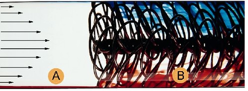
Wire matrix turbulator, known as a HiTRAN® Matrix Element, is inserted into inner tube of Heat Exchanger. The basic principle is to promote fluid mixing, convert laminar flow to turbulence flow pattern, maintaining turbulence flow pattern and improve tube-side heat transfer.
From above image,
- region (A) is laminar flow conditions
- region (B) is turbulence caused by the use of hiTRAN matrix tube Inserts
Case Studies
See below the comparison between Compressor lube oil cooler (Air-Cooled Heat Exchanger) with and without turbulator :
- Number of tube rows above each other : 5* (with turbulator) 10* (without turbulator)
- Width : 4* m(with turbulator) 7.3* m (without turbulator)
- Length : 7.9* m (with tubulator) 12.2* m (without turbulator)
- Height : 7.2* m (with turbulator) 9.3* m (without turbulator)
* For reference only
Turbulator has significantly reduce the space consume and weight and it ensure the project to proceed to installation phase. Idea of using turbulator is one of the success story in debottlenecking project especially those have space and weight constraints.
Related Post
Related Post
Labels: Air Cooler, Heat Transfer
Monday, February 16, 2009
Display problem ? Click HERE
Recommended :

Product fluid in reactor involve exothermic process is commonly hot. It is then sent to distillation and separation system for catalyst and raw material recovery. Separated product is then cooled by plant wide Cooling Water (CW) before it is sent to storage tank. The product temperature will have to be maintained.
How this temperature is controlled ?
Temperature Control Methods
There are several ways to maintain the product temperature :
- Provide a product bypass across the Cooler, control valves on Product bypass line and Outlet line (Split range control) with fixed CW flowrate
- Provide a CW bypass across the Cooler, control valves on CW bypass line and CW inlet to Cooler with full product flow across cooler
- Provide a CW bypass across the Cooler, control valves on CW bypass line and CW outlet to Cooler with full product flow across cooler
- Provide a Control valve at the Cooler inlet with full product flow across cooler
- Provide a Control valve at the Cooler outlet with full product flow across cooler
Generally the product flow is fixed by operator based on production plan and the product flow shall not be controlled. Thus, it is always not recommended to provide a control valve at the inlet and outlet of product line for product temperature control.
Disturbance of CW Network Balance
Cooling water is in a network supplying to many heat exchanger through out the plant for cooling purpose. It is normally supplied by a set of centrifugal pump. As centrifugal pump head will be affected flow across, any changes in the CW demand will affect the CW balance in network. This will further affect the pressure in the network and hence the CW flow into other heat exchangers. Thus, it is always recommended not to throttle the CW flow as much as possible to avoid CW balance.
Scaling
Throttling CW flow into heat exchanger would potential lead to low CW flow into heat exchanger, high film temperature at on CW side and promote scaling. The option (ii) and (iii) are always recommended IF throttling on CW side is chosen.
Potential affecting Production
Controlling product fluid temperature with product bypass across the Cooler, control valves on Product bypass line and Outlet line (Split range control) and fixed CW flowrate (option i) is one of the common way in temperature control for product cooling. As it minimize the impact to CW network. Nevertheless, there is still concern about manipulating product fluid or mal-operation (controller failure) of control valves would potentially lead to production lost, the option (ii) and (iii) are always the recommended option.
CW Pressurise or Non-Pressurise
Option (ii) and (iv) compare to option (iii) and (v), the difference is the location of main CW line control valve (either at the inlet or the outlet). Providing a control valve at the outlet will have the following advantages :
a) Maintain high pressure in the heat exchanger and higher pressure will results higher heat transfer
b) CW at high pressure will minimise potential of boiling
c) CW at high pressure will minimise potential release of dissolved gases in CW , trap in heat exchanger and reduce heat transfer
d) In event of Control valve failure (failed to full close position), not further Cooling. CW in the heat exchanger will be heated and potentially lead to heat exchanger overpresure due to thermal expansion and/or boiling. The CW will be relieved via Pressure Relief Device provided on the heat exchanger. Providing control valve at the outlet would allow continue CW feeding into the heat exchanger, this minimise the potential of sudden temperature increase and cause heat exchanger due to thermal shock. The downside is release CW into disposal network.
Considering above advantages, it is always recommended to provide control valve on CW line at the outlet IF throttling CW side is chooses.
CONTROLLING SHELL AND TUBE EXCHANGERS
"Controlling Shell & Tube Heat Exchanger", an excellent article by Walter Driedger discussed about all type of control schemes around heat exchanger. Check out.
Related Topic
Labels: Control, Heat Exchanger