Tuesday, February 17, 2009
Display problem ? Click HERE

Recommended :
 In one the recent depleted field debottlenecking project, new Booster Compression unit will be installed to boost the depleted well fluid pressure to meet high delivery pressure while maintaining the production forecast market demand. As this unit will be installed on existing platform, space and weight constraint are the major issues. Many efforts have been implemented in order to reduce new installation space and weight. One of them is to reduce the Lube Oil Cooler Size. One of the question raised.
How to reduce lube oil cooler size while meeting duty and flow ?
The following image demonstrates a wire matrix turbulator by hiTRAN
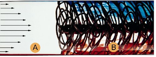
Wire matrix turbulator, known as a HiTRAN® Matrix Element, is inserted into inner tube of Heat Exchanger. The basic principle is to promote fluid mixing, convert laminar flow to turbulence flow pattern, maintaining turbulence flow pattern and improve tube-side heat transfer.
From above image,
- region (A) is laminar flow conditions
- region (B) is turbulence caused by the use of hiTRAN matrix tube Inserts
Case Studies
See below the comparison between Compressor lube oil cooler (Air-Cooled Heat Exchanger) with and without turbulator :
- Number of tube rows above each other : 5* (with turbulator) 10* (without turbulator)
- Width : 4* m(with turbulator) 7.3* m (without turbulator)
- Length : 7.9* m (with tubulator) 12.2* m (without turbulator)
- Height : 7.2* m (with turbulator) 9.3* m (without turbulator)
* For reference only
Turbulator has significantly reduce the space consume and weight and it ensure the project to proceed to installation phase. Idea of using turbulator is one of the success story in debottlenecking project especially those have space and weight constraints.
Related Post
Related Post
Labels: Air Cooler, Heat Transfer


Wednesday, February 11, 2009
Display problem ? Click HERE

Recommended :
- Subscribe FREE - Chemical Processing
- Tips on Succession in FREE Subscription
Steel picklers have traditionally used carbon block heat exchanger to heat their shallow tank high turbulence pickle baths. The multi-gasketed designs and fragile nature of graphite heat exchangers still require continuous maintenance and repair which results in expensive downtime and spare parts. This has forced the industry to look for alternatives. The use of metal shell and tube heat exchangers virtually eliminates all of the problems associated with carbon block heat exchangers.
As claimed, some of the benefits of metal shell and tube heat exchangers are :
Basic heat transfer equation used to calculate required surface area.
*Tantalum heat exchanger surface area required does not take into consideration using a higher pressure steam.
Interested in detail ? Click HERE
Download
Source : www.titanmf.com
Related Post
- Subscribe FREE - Chemical Processing
- Tips on Succession in FREE Subscription
Steel picklers have traditionally used carbon block heat exchanger to heat their shallow tank high turbulence pickle baths. The multi-gasketed designs and fragile nature of graphite heat exchangers still require continuous maintenance and repair which results in expensive downtime and spare parts. This has forced the industry to look for alternatives. The use of metal shell and tube heat exchangers virtually eliminates all of the problems associated with carbon block heat exchangers.
As claimed, some of the benefits of metal shell and tube heat exchangers are :
- Cost competitive with Carbon Block Heat Exchangers
- Easily retrofittable into existing equipment footprint
- Elimination of downtime due to equipment failure
- No spare parts to keep in inventory
- Superior corrosion resistance
- High heat transfer
- High steam pressures to reduce required surface area
- Fully welded metal design eliminates breakage during handling, installation and operation
- Elimination of acid leaks into steam condensate
| Description | Carbon block HEX | Tantalum S&T HEX |
| Heat Input(BTU) | 1,000,000 | 1,000,000 |
| Steam Pressure (PSI) | 75 | 75 |
| Typical Overall U (BTU/hrft2.F) | 250 | 650 |
| Surface Area Required (Sq. Ft.) | 29* | 11.2* |
| Inventory of Spare Parts Required | YES | NO |
| Fully Welded Metal Design | NO | YES |
Basic heat transfer equation used to calculate required surface area.
*Tantalum heat exchanger surface area required does not take into consideration using a higher pressure steam.
Interested in detail ? Click HERE
Download
Source : www.titanmf.com
Related Post
Labels: Heat Exchanger, Heat Transfer
Sunday, August 24, 2008
Display problem ? Click HERE
Recommended :
- Subscribe FREE - Chemical Processing
- Tips on Succession in FREE Subscription
Heating system is one of the common utilities in a gas processing, LNG production, refining plant, etc. Heating medium commonly used are Heating oil, thermal fluid, water, etc. In circulating thermal-fluid heating systems, the heat transfer rate is typically controlled to maintain a desired outlet-temperature setpoint of the fluid. However, it is the temperature of the fluid film in contact with the heater walls instead of bulk fluid temperature that often is the key factor affecting fluid life, system fouling, and overall equipment performance.
CE and Solutia are organizing a webinar on Heat Flux & Film Temperature. The webinar presenter is Robert Pelini, P.E., President of RGP Engineering, LLC. who has more than 24 years experience in the design of fired heaters and heat recovery systems and has authored numerous technical articles and
publications on process equipment and energy systems design.
 The webinar will discuss :
- Subscribe FREE - Chemical Processing
- Tips on Succession in FREE Subscription
Heating system is one of the common utilities in a gas processing, LNG production, refining plant, etc. Heating medium commonly used are Heating oil, thermal fluid, water, etc. In circulating thermal-fluid heating systems, the heat transfer rate is typically controlled to maintain a desired outlet-temperature setpoint of the fluid. However, it is the temperature of the fluid film in contact with the heater walls instead of bulk fluid temperature that often is the key factor affecting fluid life, system fouling, and overall equipment performance.CE and Solutia are organizing a webinar on Heat Flux & Film Temperature. The webinar presenter is Robert Pelini, P.E., President of RGP Engineering, LLC. who has more than 24 years experience in the design of fired heaters and heat recovery systems and has authored numerous technical articles and
publications on process equipment and energy systems design.
- The importance of fluid film temperature
- Variables that affect film temperature, with specific emphasis on heat flux at the metal surfaces
- Various types of fired and electric thermal fluid heater designs and estimation of their heat flux rates
- Heat flux rates in convective thermal fluid heaters
- How to estimate or check peak fluid film temperature
- Common problems and how to avoid them
- Therminol Reference Disk - Assist you to Optimize your Heat Transfer System
- FAYF - Useful Heat Transfer Equation
- Few Tips on Energy Efficient & Recovery
- Heat Transfer - Internal and External Flow
- FREE E-book........A Heat Transfer Textbook
Labels: Heat Transfer
Monday, October 1, 2007
Can't view properly ? Click HERE
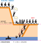 Chemical & Process plant is energy intensive industry. However, so far waste energy in the form of heat, noise, vibration, etc is dissipated to environment without or with some level of recovery. Example of heat recovery is the waste heat recovery unit (WHRU) located at the Gas turbine flue gas outlet, economizer at the boiler flue gas outlet, etc. Generally the flue gas exit temperature still rather high i.e. 250 degC, as compare to ambient temperature of 30 degC, believe there is still heat can be recovered from temperature perspective. But how much energy can be recovered and it this worth for recovery ? How to measure quantity of heat recovered to generate work ?
Exergy is the term to measure the capability of a hot fluid to produce work.
Above article has described a simplified approach to evaluate the exergy content of a hot waste and estimate amount of useful energy can be recovered from waste gases.
Related Topics
Chemical & Process plant is energy intensive industry. However, so far waste energy in the form of heat, noise, vibration, etc is dissipated to environment without or with some level of recovery. Example of heat recovery is the waste heat recovery unit (WHRU) located at the Gas turbine flue gas outlet, economizer at the boiler flue gas outlet, etc. Generally the flue gas exit temperature still rather high i.e. 250 degC, as compare to ambient temperature of 30 degC, believe there is still heat can be recovered from temperature perspective. But how much energy can be recovered and it this worth for recovery ? How to measure quantity of heat recovered to generate work ?Exergy is the term to measure the capability of a hot fluid to produce work.
Raynald Labrecque & Kiari Goni Boulama
Above article has described a simplified approach to evaluate the exergy content of a hot waste and estimate amount of useful energy can be recovered from waste gases.
Related Topics
Labels: Exergy, Heat Recovery, Heat Transfer
Monday, August 20, 2007

Basic heat transfer relationships is apply to Air-Cooled Heat Exchanger (ACHE). The fundamental heat ransfer equation :
Q = U. A. LMTD.F
where
U = overall heat transfer coefficientA = Heat transfer area
LMTD = Log mean temperature difference
F = Correction factor
Typical heat transfer coefficient for Air-Cooled Heat Exchangers
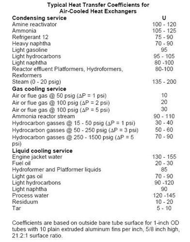
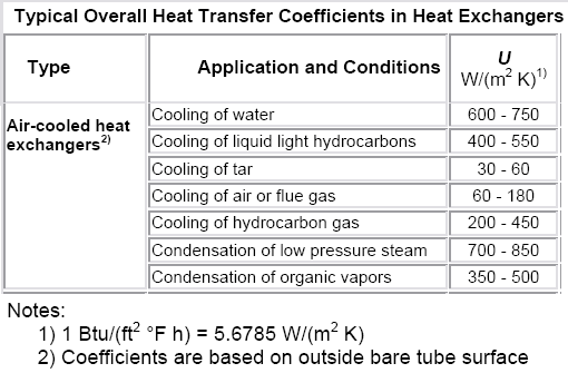
Source : DELTA T
Labels: Air Cooler, Heat Exchanger, Heat Transfer, Shell and Tube Heat Exchanger
Friday, August 17, 2007
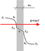
Generic Heat Transfer equation in heat exhanger,
Q = U.A.LMTD.F
where
Q = Rate of heat transfer
U = Mean overall heat transfer coefficient
A = Heat transfer surface area
LMTD = Log mean temperature difference
F = Correction factor
LMTD = (DT1-DT2) / Ln (DT1-DT2)
Where
DT1 = Th,i - Tc,o
DT2 = Th,o-Tc,i
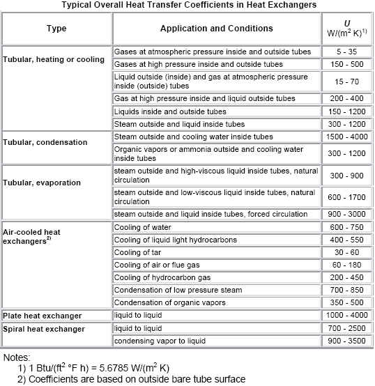
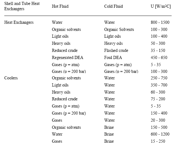
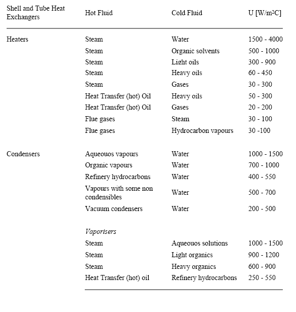
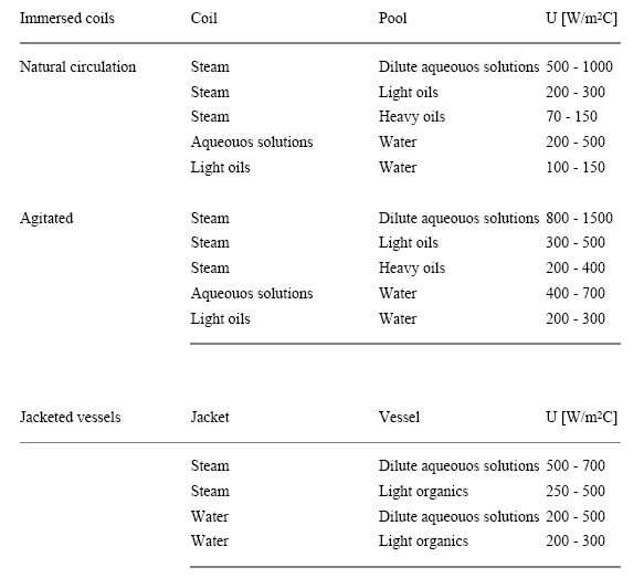
For a given heat transfer service with known mass flow rates and inlet and outlet temperatures the determination of Q is straightforward and ΔT can be easily calculated if a flow arrangement is selected (e.g. logarithmic mean temperature difference for pure countercurrent or cocurrent flow). This is different for the overall heat transfer coefficient U. The determination of U is often tedious and needs data not yet available in preliminary stages of the design. Therefore, typical values of U are useful for quickly estimating the required surface area. The literature has many tabulations of such typical coefficients for commercial heat transfer services. Below are tabulation of U value for different applications and heat exchanger types.

Related reading
Labels: Heat Transfer